
Original Post Author: Don C. Weber [Twitter: @cutaway]
Original Date Published: 08 April 2013
Accessing memory from embedded devices can be accomplished multiple ways. The easiest methods include using debugging ports or tapping the exposed pins of a Thin small-outline packages (TSOP) memory component. One of the more challenging memory acquisitions are those that involve memory components with Fine Ball Grid Array (FBGA) or Very-thin Fine Ball Grid Array (VFBGA) packaging. Pulling memory from these type of components takes special hardware. My preference is the Xeltek SuperPro 5000, basically because InGuardians bought me one.
Acquiring the memory starts by identifying the memory component and determining the number of balls in the array. Once you know the specific component you can determine which adapter is required for your acquisition device. For the Xeltek SuperPro 5000 the adapters run about $500. The good news is, even if Xeltek does not have an adapter for the component you can contact them and they may be able generate a new adapter quickly for about the same cost.
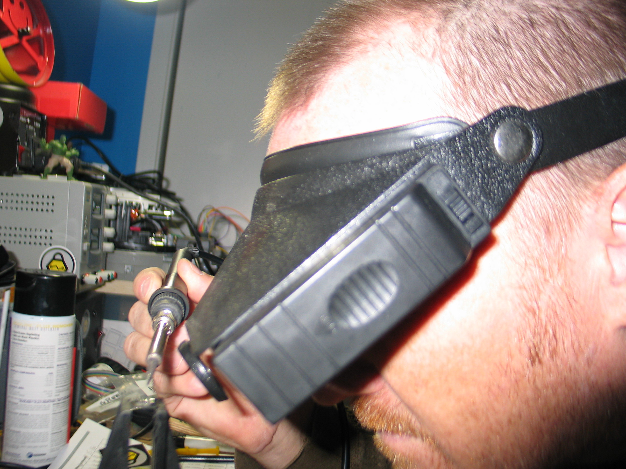
Your next step is to remove the component. For this you will need a hot air gun. You can purchase these separately or you can get a complete soldering and rework station such as the Aoyue 968A+ Hot Air Rework Station. Figure 0x00 is an image of me pretending to remove a chip from my Goodfet 41 (since I forgot to take pictures of me removing the FBGA component).
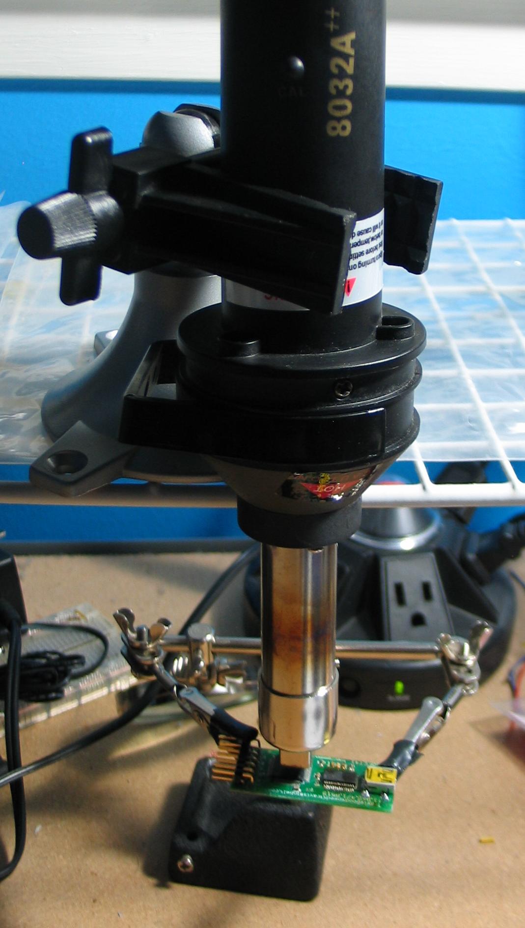
Figure 0x00: Removing FBGA Memory Component from Board (sorta)
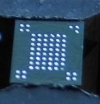
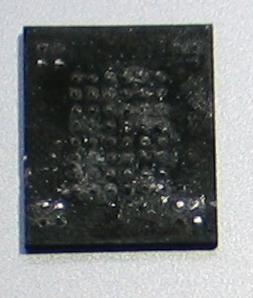
Once we have the memory chip removed there may be some solder left on the pins. Some of this solder may bridge several of the pads. Figure 0x01 shows what the FBGA memory component looks like after some solder wick was used to remove the excess solder which provided clean pads.
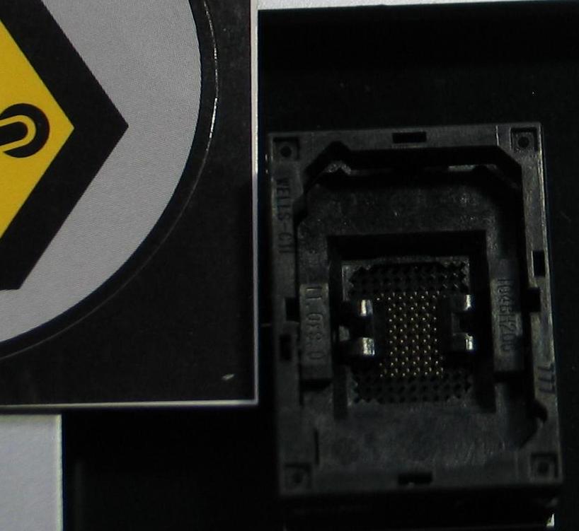
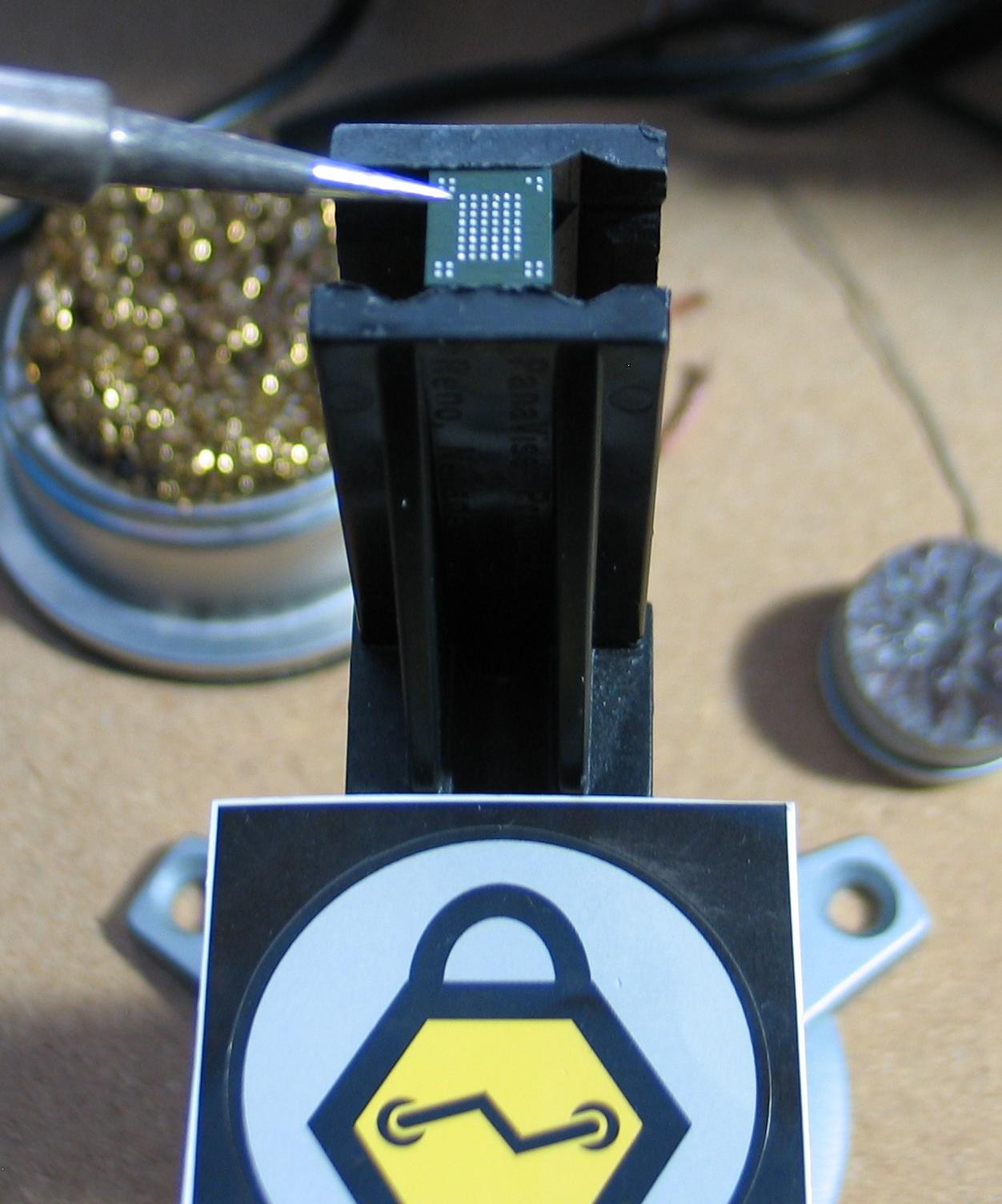
The next step is to put the memory component in the Xeltek socket adapter. As you can see in Figure 0x02, this adapter has little grabbers that will grip the balls on the bottom of the memory component. These grabbers open and close when you push down on the spring-sides of the socket adapter.
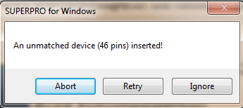
Ok, +1 to any of you who already figured out a problem with this process. For those of you who didn’t, the “grabbers” grip the “balls” of the memory component. We removed the solder down to the pads when the solder was cleaned off. Thus, there is nothing for the “grabbers” to grip. When there is nothing to grip the Xeltek software gives a nice error message explaining the problem. It either says “No device in the socket.” Or, as can be seen in Figure 0x03, that it has encountered an unmatched device.
This process takes a lot of patience, a magnifying headset, a fine-pointed soldering tip, and multiple attempts. Figures 0x04 and 0x05 are images of me soldering the balls back onto the pads of a memory component I have worked on recently.
Before we continue I do have some quick recommendations for attempting this procedure.
- Use a clamp. You will not be able to hold this component still without one. As the solder grabs a pad it might move the component and either bridge or wipe away solder on other pads.
- Don’t use any flux unless the solder absolutely will not stay on the pad. Flux is helpful when working with larger components or components with more space between pads. But for this work the flux will actually make it difficult to see the pads and work with the small amounts of solder that you need.
- Use tiny bits of solder on the end of a fine-pointed soldering tip. I would just touch the end of my solder wire and then gently tap the pad that I needed. Sometimes if I had too much it would get on two or more pads. Gently work the excess away.
- You are not going to be able to make little balls. Try to make little points, emphasis on little. Make sure the points are going straight up. Points going off to the side might catch on the grippers or touch them creating a bridge you will never see.
- Be patient and take a break if you need to. This is tough and requires a steady hand. You can always come back to it.
- Consider using solder paste and a hot plate or hot air gun. With the hot air gun you will need to be careful of the fan speed or you will blow the solder around. Also, the solder paste might get sucked away from some of the pads as it heats up. You may have to augment this technique with hand soldering.
- Don’t get your iron too hot for this. If you damage the pads or they come off you won’t be able to fix it like you can most other integrated circuit boards.
Figure 0x06 is what it looks like after soldering the tiny points to the pads. It is the best image I could get showing the results of this process. You’ll know it when you see it in your magnifying glass.
Once you are done soldering the memory component is ready to be placed back into the Xeltek socket adapter. Most likely you will be greeted with the following message (Figure 0x07) when you attempt to dump the data.
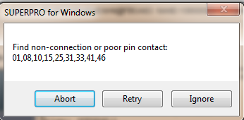
This means that the socket adapter does not have a good connection for these pins. Although you can choose to ignore this message and proceed with the read, the read will most likely fail. You could double check which pins map to important communications components for the chip, but you will most likely still have issues. You can also pull the component out and do some more solder work (cause most likely you missed one or two pads or didn’t get the tiny points just right). But, as shown in Figure 0x08, there is also the “pencil method.”
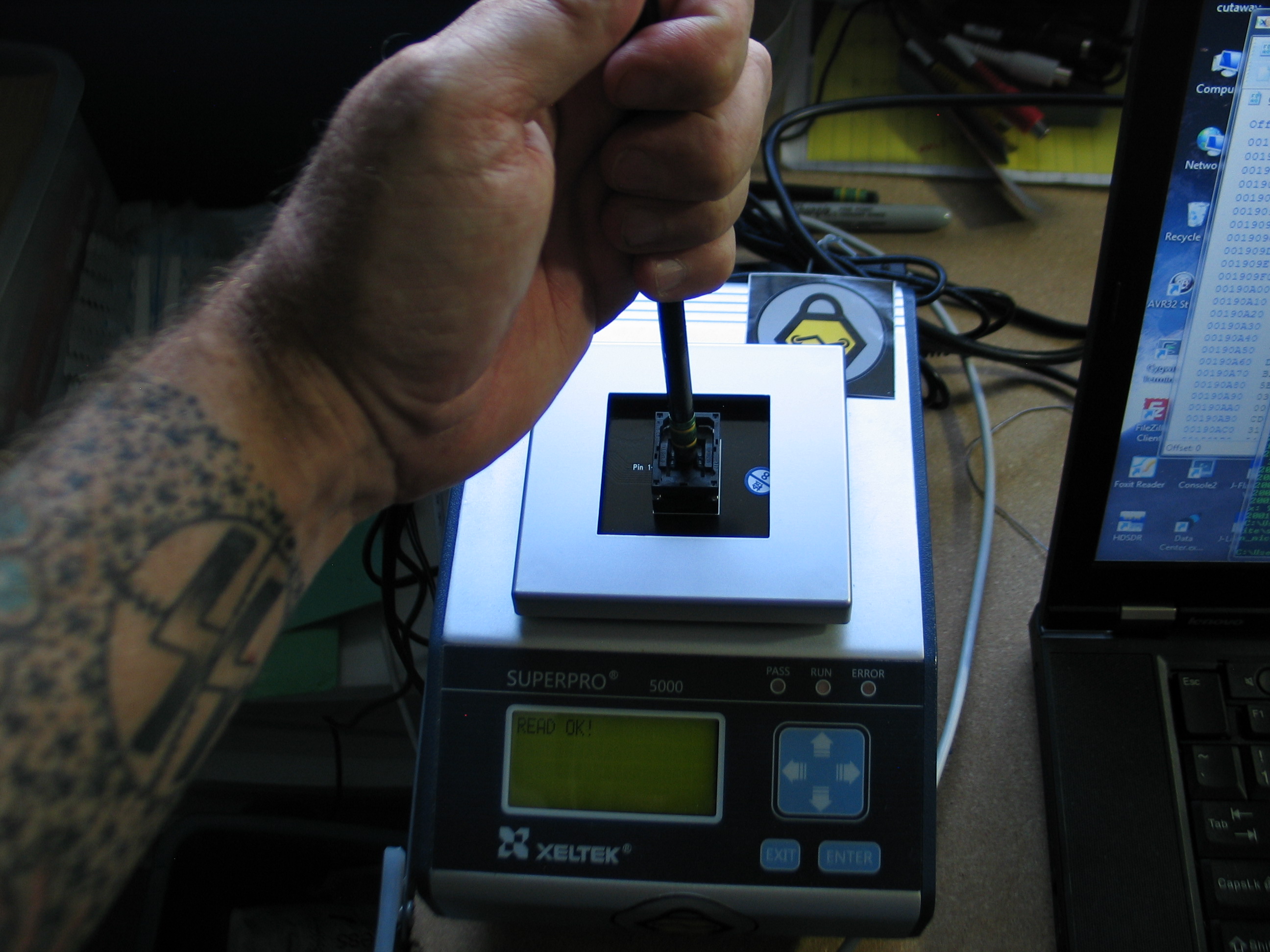
This method works well, but you do have to be careful or you may damage your socket adapter. First the pencil can be used to slightly shift the memory component in the adapter. This may be enough to ensure that the grippers grip the appropriate pins. Push down on the spring-sides of the adapter to open the grippers (very important), shift the chip a bit, and then set the chip by letting go of the sides. If you still get pin errors you can push down on the spring-sides, apply gentle but constant pressure with the pencil, and set the chip. Do not let up on the pencil’s pressure or you will loose the connection. Click read in the software and if all goes well the Xeltek will start dumping the memory contents. Depending on the size of the memory this could take a few seconds or even a few minutes. Once completed you should be rewarded with a successful read message from the Xeltek device and software.
After you save off the data you can analyze it with your favorite memory analysis techniques. You’ll most likely be looking for firmware, certificates, keys, filenames, IP addresses, email addresses, and any other interesting strings that might help you with other portions of your embedded device analysis.
I hope this helps.
Go forth and do good things.