
Date Published: 26 July 2013
In May 2013 Jay Radcliffe decided that he wanted InGuardians to do something special for Black Hat USA 2013 and DefCon 21 and thus Sparring Board Version 1.2 – Raspberry Pi Edition (SBv1.2) was born. His original idea was to provide users with a easy method to interact with the Raspberry Pi’s UART interface via USB. He wanted large SMB components to make it easy to solder. He also thought having a small breakout board so that users could easily test new ideas would be helpful. After a little more brain storming it was also decided that breaking out the General Purpose Input/Output (GPIO) pins so that they were labeled and in a logical order would also be helpful for project development and interactions with the Pi.
The SBv1.2 when through several additions. Normally embedded development is done by hand drawing the schematic, purchasing through-hole components, and testing/tweaking the initial thoughts using a bread board to create the circuit. We did not have time for that if we wanted to be ready for Black Hat and DefCon. Instead we dove right into developing the board using Eagle Cad, information posted by Raspberry Pi’s GPIO pinout, and the circuits provided by FTDI for their FTDI RS232 chip. We originally thought about following the FTDI configuration used by they Goodfet project and we purchased a test run of SBv1.0 to test the Sparring Board concept.
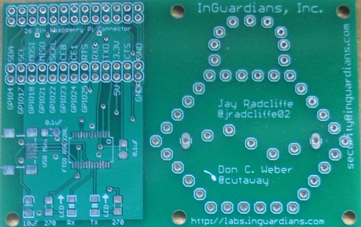
Figure 0x00: Sparring Board v1.0 – Front
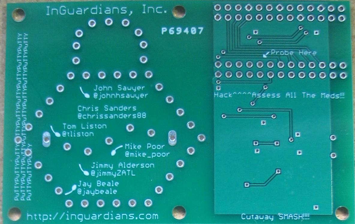
Figure 0x01: Sparring Board v1.0 – Back
Testing of SBv1.0 went very well and proved that the boards fit on the Raspberry Pi very nicely. Jay had just met Joe Grand out at Black Hat Design West and asked him for a few pointers. Joe reminded us that traces should not make right angle turns and he also recommended that we follow the FTDI specifications for the FTDI circuit. Thus SBv1.1 was generated. A quick test run confirmed that the new traces and FTDI configuration worked. We also included the finalized silk screen for both the front and back of the boards. With this success InGuardians management approved the 300 boards with 125 boards to include the necessary components.
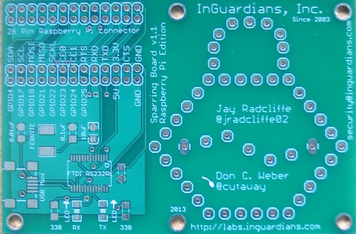
Figure 0x02: Sparring Board v1.1 – Front
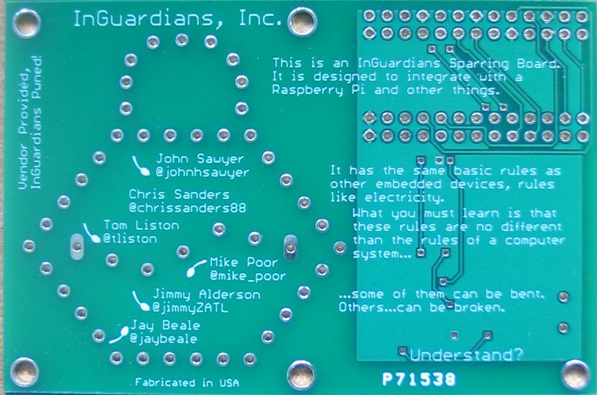
Figure 0x03: Sparring Board v1.1 – Back
For the final run of SBv1.2 we only needed to specify that the boards were blue and the silkscreen was yellow. Very important features for any InGuardians project.
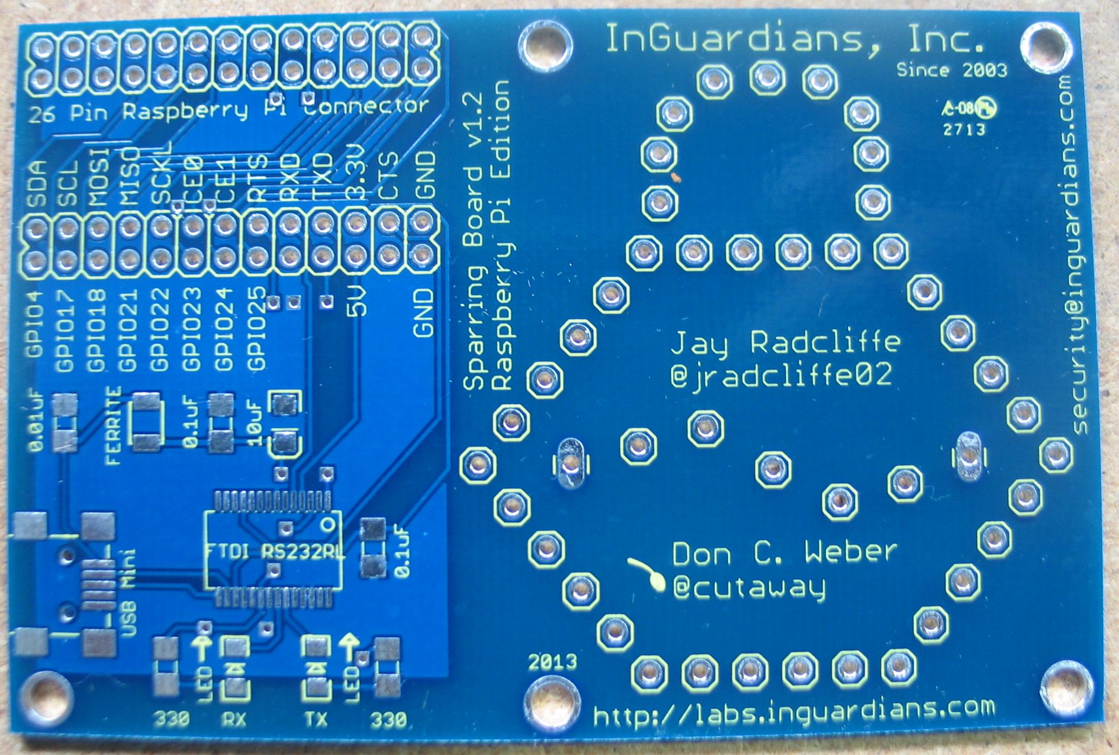
Figure 0x04: Sparring Board v1.2 – Front
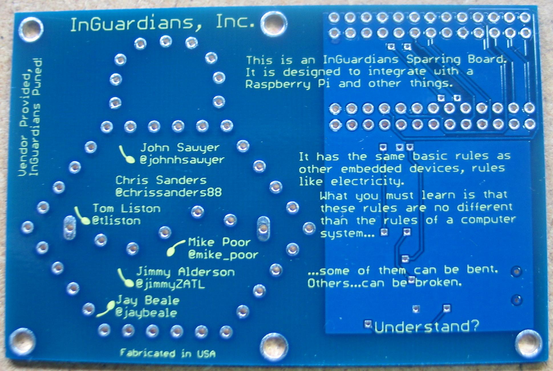
Figure 0x05: Sparring Board v1.2 – Back
We hope you enjoy this version of the Sparring Board and we are looking forward to your input about this and future Sparring Board projects. You can find information about each of these projects as they are developed at the InGuardians Sparring Boards GitHub repository.
Of course, every embedded project needs an example where people can start. The InGuardians Sparring Boards GitHub repository has a Projects directory with a few C-based program files that will allow you to communicate with the Raspberry Pi’s serial console to send and receive data and interact with the GPIO pins. Read the comments in each file, figure out which one you would like to start with, upload the files to your Raspberry Pi via SSH, compile the programs according to the notes, and you have started using the Sparring Board. Next step is to expand it using your own ideas. Good luck.
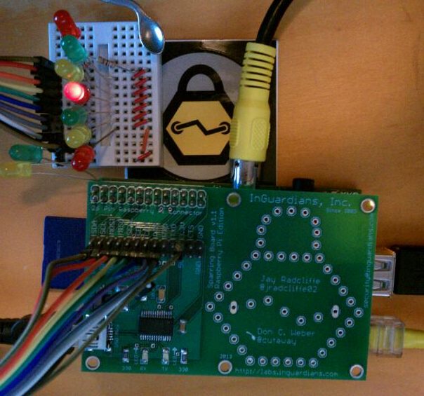
Figure 0x06: LED Flashing Project